Half wave rectifier experiment pdf
If you follow the current path through a full wave rectifier you will notice that when V in goes positive, D 2 and D 4 are on (conducting), while D 1 and D 3 are off, and current flows in the direction through the resistor as indicated by the arrow.
The efficiency of the half wave rectifier is also limited because only half the sinusoidal waveform is being converted to the DC signal. Losing this half of the signal can be comparable to losing energy..
2/12/2016 · This is a lab experiment of Half Wave. We are not professional. It was a class practice. Thank You 🙂
Full wave rectifiers have some fundamental advantages over their half wave rectifier counterparts. The average (DC) output voltage is higher than for half wave rectifier, the output of the full wave rectifier has much less ripple than that of the half wave rectifier producing a smoother output waveform.
Suat SELIM 2. Objectives: ¾ To recognize a half-wave rectified sinusoidal voltage. ¾ To understand the term ‘mean value’ as applied to a rectified waveform.
Rectifier Circuits 2 Chapter 2.1 EXPERIMENTS IN RECTIFIERS 2.1.1 Aim of the Experiment To construct the following circuits, observe respective waveforms, and make relevant measurements: a. Half-wave rectifier b. Full-wave rectifier (using centre-tapped transformer)
Now select the experiment Half Wave Rectifier from the experiment list. After selecting the experiment you will see the schematic and breadboard circuit diagram. The bread board circuit diagram is an example how to connect components on board.
3. diodes and diode circuits tlt-8016 basic analog circuits 2005/2006 8 half – wave rectifier with smoothing capacitor figure 3.12a half-wave rectifier with smoothing…
Experiment 4 Half-Wave Rectifier Circuit 1- Objects of the Experiment – Recording the output voltage for an Ohmic load resistance – Representing the output voltage as a function of the charging capacitor. – Representing the output voltage as a function of the load resistor. 2- Principles Rectification is the process of converting an alternating (AC) voltage into one that is limited to one
The single-phase half-wave controlled rectifier uses a single thyristor with a load and also the output voltage and current waveform as shown in figure 1 . In a positive half cycle of
half-wave rectifier AIM: To Rectify the AC signal and then to find out Ripple factor and percentage of Regulation in Half wave rectifier with and without Capacitor filter.
This simulation plots the input voltage as a sine wave and the output voltage as a series of “humps” corresponding to the positive half-cycles of the AC source voltage. The dynamics of a DC motor are far too complex to be simulated using SPICE, unfortunately.
EE/CE 3111 Electronic Circuits Laboratory Spring 2015 Professor Y. Chiu 3 Full-Wave Rectifier Figure 2-3: Full-wave rectifier 1. Use PSpice to obtain a plot of …
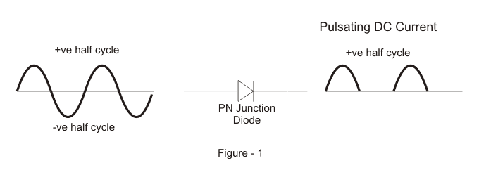
The Half wave rectifier is a circuit, which converts an ac voltage to dc voltage. In the Half wave rectifier circuit shown above the transformer serves two purposes. It can be used to obtain the desired level of dc voltage (using step up or step down transformers).
PSPICE tutorial: Half-wave rectifier In this tutorial, we will simulate a simple half-wave rectifier circuit. This tutorial comes with relatively little commentary.
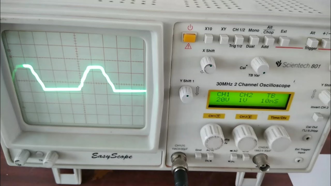
Conclusion. In part 1 experiment 1 , we have conducted an experiment. It is half-wave rectifier circuit. We can observe that there is a peak-to-peak waveform and we have been noticed that is …
Half Wave Rectifier e-VALIDATE

AC to DC Experiment (1) education.curent.utk.edu
EXPERIMENT 1 SINGLE-PHASE FULL-WAVE RECTIFIER AND LINEAR REGULATOR Introduction: In this experiment groups will perform the construction of a basic AC-DC converter (rectifier) circuit. This is a simple example of a regulated DC power supply. You will see an application of one of the basic switching elements (diode) studied in the course. Employing a basic regulator integrated circuit (IC), …
The electrical symbol for a diode is and the arrow is in the forward direction which has a low resistance. Sometimes on the physical diode, all you see is a band and this represents the bar in the above symbol.
Then a halve-wave rectifier is described performing full control of the conducting angle. It incorporates a phase shifter implemented in the gate circuit of the thyristor. Using this a full wave rectifier is described and its characteristics extracted by simulation. The main andvantage of the new circuit is its ability to control the conducting angle in its full range making the rectifier
Using signal generator apply the voltage at high frequency to a half wave diode rectifier and observe the response with resistive load and sketch output voltage. Comment on the response at high frequency
Single-Phase half wave Rectifier Experiment aim The aim of this experiment is to design and analysis of a single phase uncontrolled rectifier. Apparatus Make the circuit for AC-DC converter using the following parts: 1- Power electronic trainer 2- Oscilloscope 3- AVO meter Theory Rectification is the process of conversion of alternating input voltage to direct output voltage. In diode
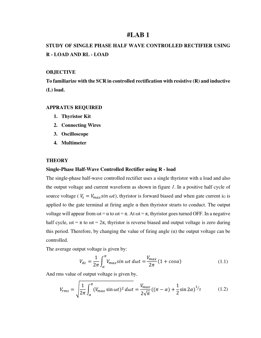
Rectifiers yield a unidirectional but pulsating direct current; half-wave rectifiers produce far more ripple than full-wave rectifiers, and much more filtering is needed …
LIST OF EXPERIMENTS Sr. No. EXPERIMENTS Date Of Performance Date Of Submission. Teacher ˇs Signature 1. To construct a zener diode voltage regulator. 2. Study of Half Wave rectifier.
Power Electronics Laboratory Reg. No. _____ Session 2011 Seventh Semester EED,UET, Lahore Experiment No. 2 Half Wave Rectifier using RC-Triggering
26/06/2009 · Using the half wave rectifier cuts the voltage in half. Im looking for a method to keep the voltage in half but still use the full sinewave. Hence the polarity inverter question. If you could half wave rectify both the positive and the negative part of the sinewave from the inverter and then invert the polarity on one you should have the same potential albeit with a time difference. Them

In this experiment, we will study three different types of rectifiers with capacitor filter. Half Wave Rectifier: This is the simplest rectifier that uses a single diode and a load resistor.
Half Wave Rectifier 4-Procedure: 1. Connect the circuit as shown in Fig.1, adjust the power supply at 10 V. 2. Measure the input voltage V 1 and the output voltage V
EECS 100 Spring 2004 Muthuswamy, Bharathwaj 6 Figure 8. Half-Wave Rectifier with threshold voltage model when the diode is forward biased. Hence, the effect of the diode is to drop a voltage of v
Half-Wave-Rectifier_ — Overview Objective: After performing this experiment student must be able to Understand the Circuit behaviour the Half wave Rectifier
i-2 A diode-based rectifier is shown in Figure 2. A half-wave rectifier will be setup in this experiment and it rectifies only the positive half of the wave.
The circuit is called a “half wave rectifier” since only one half, in this case the positive half, of the input appears at the output. Note that R11=1.5k in our Graymark power supply. 4) CAPACITIVE FILTER Now connect the circuit in Fig. 2, using a 10 µf capacitor from your Graymark kit. A procedure for doing this is described in steps 3 and 4 on page 30 where you are asked to solder the
Experiment No. 5 FULL-WAVE RECTIFIERS AND POWER SUPPLIES Objective: The objective of this experiment is to study the performance and characteristic of full-wave rectifiers and DC power supplies utilizing Zener diode as a voltage stabilizing device. The performance of the full-wave rectifier will be studied and measured as well as that of the Zener diode. Introduction: One of the important

The full wave rectifier consists of two half wave rectifier circuits with common load. These are connected in such a way that conduction takes place through two diodes in alternate half-cycles and current through the load is sum of two currents.
8.2.1 Half-Wave Rectifier In order to understand the operation of the half-wave rectifier, consider the circuit shown in Figure 8.2. In this circuit, the transformer secondary output is represented as an
There are two types of rectifier circuits, half-wave (uses only the positive cycle of the AC signal) and full-wave (uses both cycles of the AC signal), but this experiment will focus on full-wave because it is more widely used in real world applications.
Lab Report Solayman EWU
Experiment 6, 7 & 8: To verify the working of a Half wave rectifier, Full wave rectifier and fullwave bridge rectifier and to measure the ripple factor. Experiment 9 & 10: To design Series and Shunt Voltage regulator Experiment 11:
wave diode rectifier are replaced by power thyristors. With this lab you will understand the characteristics of three phase full wave full controlled rectifier, measure the voltage and current values.
Rectifier circuits PHYWE series of Set up the experiment on the universal plug-board in accord-ance with Fig. 1 and the circuit diagrams in Figs. 2 to 5. The output current is varied by the load resistor RL. Care should be taken that the current does not exceed the maxi-mum permissible lA through the silicon diodes. Theory and evaluation 1. In a half-wave rectifier (Fig. 2), only the
Lab 5, Diodes 3 Part II: Half Wave Rectifier Power generators usually produce AC voltages since they are most convenient for power transmission.
The Half wave rectifier is a circuit, which converts an ac voltage to dc voltage. It can be used to It can be used to obtain the desired level of dc voltage (using step up or step down transformers). – iso 7010 safety signs pdf
Conclusion Scribd
Half Wave Rectifier Lab Experiment (Bangla) YouTube

Dual halfwave rectifier polarity inverter Physics Forums
EXPERIMENT 1 SINGLE-PHASE FULL-WAVE RECTIFIER AND
Diodes Experiment Guide inst.eecs.berkeley.edu
EXPERIMENT 3 Half Wave and Full Wave PDF documents
Experiment No. 5 Single Phase Uncontrolled Rectifier
Half-wave Rectifier Discrete Semiconductor Circuits
– EXPERIMENT 5 DIODES AND RECTIFICATION
CIRCUITS LABORATORY Experiment 8

Experiment 4 Half-Wave Rectifier Circuit Imam U
Half Wave Rectifier e-VALIDATE
Experiment 4 Half-Wave Rectifier Circuit Imam U
Half Wave Rectifier 4-Procedure: 1. Connect the circuit as shown in Fig.1, adjust the power supply at 10 V. 2. Measure the input voltage V 1 and the output voltage V
3. diodes and diode circuits tlt-8016 basic analog circuits 2005/2006 8 half – wave rectifier with smoothing capacitor figure 3.12a half-wave rectifier with smoothing…
8.2.1 Half-Wave Rectifier In order to understand the operation of the half-wave rectifier, consider the circuit shown in Figure 8.2. In this circuit, the transformer secondary output is represented as an
The efficiency of the half wave rectifier is also limited because only half the sinusoidal waveform is being converted to the DC signal. Losing this half of the signal can be comparable to losing energy..
Rectifier circuits PHYWE series of Set up the experiment on the universal plug-board in accord-ance with Fig. 1 and the circuit diagrams in Figs. 2 to 5. The output current is varied by the load resistor RL. Care should be taken that the current does not exceed the maxi-mum permissible lA through the silicon diodes. Theory and evaluation 1. In a half-wave rectifier (Fig. 2), only the
Using signal generator apply the voltage at high frequency to a half wave diode rectifier and observe the response with resistive load and sketch output voltage. Comment on the response at high frequency
The full wave rectifier consists of two half wave rectifier circuits with common load. These are connected in such a way that conduction takes place through two diodes in alternate half-cycles and current through the load is sum of two currents.
The Half wave rectifier is a circuit, which converts an ac voltage to dc voltage. In the Half wave rectifier circuit shown above the transformer serves two purposes. It can be used to obtain the desired level of dc voltage (using step up or step down transformers).
This simulation plots the input voltage as a sine wave and the output voltage as a series of “humps” corresponding to the positive half-cycles of the AC source voltage. The dynamics of a DC motor are far too complex to be simulated using SPICE, unfortunately.
wave diode rectifier are replaced by power thyristors. With this lab you will understand the characteristics of three phase full wave full controlled rectifier, measure the voltage and current values.
Half-Wave-Rectifier_ — Overview Objective: After performing this experiment student must be able to Understand the Circuit behaviour the Half wave Rectifier
Experiment No. 5 Single Phase Uncontrolled Rectifier
Experiment No. 2 Half Wave Rectifier using RC-Triggering
This simulation plots the input voltage as a sine wave and the output voltage as a series of “humps” corresponding to the positive half-cycles of the AC source voltage. The dynamics of a DC motor are far too complex to be simulated using SPICE, unfortunately.
Power Electronics Laboratory Reg. No. _____ Session 2011 Seventh Semester EED,UET, Lahore Experiment No. 2 Half Wave Rectifier using RC-Triggering
The Half wave rectifier is a circuit, which converts an ac voltage to dc voltage. It can be used to It can be used to obtain the desired level of dc voltage (using step up or step down transformers).
EE/CE 3111 Electronic Circuits Laboratory Spring 2015 Professor Y. Chiu 3 Full-Wave Rectifier Figure 2-3: Full-wave rectifier 1. Use PSpice to obtain a plot of …
26/06/2009 · Using the half wave rectifier cuts the voltage in half. Im looking for a method to keep the voltage in half but still use the full sinewave. Hence the polarity inverter question. If you could half wave rectify both the positive and the negative part of the sinewave from the inverter and then invert the polarity on one you should have the same potential albeit with a time difference. Them
half-wave rectifier AIM: To Rectify the AC signal and then to find out Ripple factor and percentage of Regulation in Half wave rectifier with and without Capacitor filter.
Half Wave Rectifier e-VALIDATE
PSPICE tutorial Half-wave rectifier
i-2 A diode-based rectifier is shown in Figure 2. A half-wave rectifier will be setup in this experiment and it rectifies only the positive half of the wave.
EXPERIMENT 3 Half Wave and Full Wave PDF documents
EXPERIMENT 1 SINGLE-PHASE FULL-WAVE RECTIFIER AND
Experiment 4 Half-Wave Rectifier Circuit Imam U
The efficiency of the half wave rectifier is also limited because only half the sinusoidal waveform is being converted to the DC signal. Losing this half of the signal can be comparable to losing energy..
Chapter Rectifier Circuits PVT
Diodes Experiment Guide inst.eecs.berkeley.edu
Half-Wave-Rectifier_ — Overview Objective: After performing this experiment student must be able to Understand the Circuit behaviour the Half wave Rectifier
Experiment 4 Half-Wave Rectifier Circuit Imam U
Half Wave Rectifier Lab Experiment (Bangla) YouTube
Suat SELIM 2. Objectives: ¾ To recognize a half-wave rectified sinusoidal voltage. ¾ To understand the term ‘mean value’ as applied to a rectified waveform.
Lab 2 V2 Case Western Reserve University
Lab Report Solayman EWU
Rectifier Circuits 2 Chapter 2.1 EXPERIMENTS IN RECTIFIERS 2.1.1 Aim of the Experiment To construct the following circuits, observe respective waveforms, and make relevant measurements: a. Half-wave rectifier b. Full-wave rectifier (using centre-tapped transformer)
Half Wave Rectifier e-VALIDATE
Lab Report Solayman EWU
EXPERIMENT 1 SINGLE-PHASE FULL-WAVE RECTIFIER AND
26/06/2009 · Using the half wave rectifier cuts the voltage in half. Im looking for a method to keep the voltage in half but still use the full sinewave. Hence the polarity inverter question. If you could half wave rectify both the positive and the negative part of the sinewave from the inverter and then invert the polarity on one you should have the same potential albeit with a time difference. Them
Experiment 4 Half-Wave Rectifier Circuit Imam U
Using signal generator apply the voltage at high frequency to a half wave diode rectifier and observe the response with resistive load and sketch output voltage. Comment on the response at high frequency
PSPICE tutorial Half-wave rectifier
Half-wave Rectifier Discrete Semiconductor Circuits
Rectifiers yield a unidirectional but pulsating direct current; half-wave rectifiers produce far more ripple than full-wave rectifiers, and much more filtering is needed …
Half Wave Rectifier Lab Experiment (Bangla) YouTube
Chapter Rectifier Circuits PVT
There are two types of rectifier circuits, half-wave (uses only the positive cycle of the AC signal) and full-wave (uses both cycles of the AC signal), but this experiment will focus on full-wave because it is more widely used in real world applications.
Experiment No.3 Single-Phase half wave Rectifier
EXPERIMENT 5 DIODES AND RECTIFICATION
Diodes Experiment Guide inst.eecs.berkeley.edu
This simulation plots the input voltage as a sine wave and the output voltage as a series of “humps” corresponding to the positive half-cycles of the AC source voltage. The dynamics of a DC motor are far too complex to be simulated using SPICE, unfortunately.
EXPERIMENT 5 DIODES AND RECTIFICATION
EECS 100 Spring 2004 Muthuswamy, Bharathwaj 6 Figure 8. Half-Wave Rectifier with threshold voltage model when the diode is forward biased. Hence, the effect of the diode is to drop a voltage of v
Half Wave Rectifier Lab Experiment (Bangla) YouTube
Lab Report Solayman EWU
i-2 A diode-based rectifier is shown in Figure 2. A half-wave rectifier will be setup in this experiment and it rectifies only the positive half of the wave.
AC to DC Experiment (1) education.curent.utk.edu
Conclusion. In part 1 experiment 1 , we have conducted an experiment. It is half-wave rectifier circuit. We can observe that there is a peak-to-peak waveform and we have been noticed that is …
Experiment 4 Half-Wave Rectifier Circuit Imam U
The full wave rectifier consists of two half wave rectifier circuits with common load. These are connected in such a way that conduction takes place through two diodes in alternate half-cycles and current through the load is sum of two currents.
Experiment No. 5 Single Phase Uncontrolled Rectifier
Half Wave Rectifier e-VALIDATE
CIRCUITS LABORATORY Experiment 8
Using signal generator apply the voltage at high frequency to a half wave diode rectifier and observe the response with resistive load and sketch output voltage. Comment on the response at high frequency
Diodes Experiment Guide inst.eecs.berkeley.edu
The efficiency of the half wave rectifier is also limited because only half the sinusoidal waveform is being converted to the DC signal. Losing this half of the signal can be comparable to losing energy..
PSPICE tutorial Half-wave rectifier
Experiment 6, 7 & 8: To verify the working of a Half wave rectifier, Full wave rectifier and fullwave bridge rectifier and to measure the ripple factor. Experiment 9 & 10: To design Series and Shunt Voltage regulator Experiment 11:
EXPERIMENT 2 HALF-WAVE & FULL- WAVE RECTIFICATION F A
Diodes Experiment Guide inst.eecs.berkeley.edu
Half Wave Rectifier 4-Procedure: 1. Connect the circuit as shown in Fig.1, adjust the power supply at 10 V. 2. Measure the input voltage V 1 and the output voltage V
EXPERIMENT 1 SINGLE-PHASE FULL-WAVE RECTIFIER AND
Experiment No. 5 Single Phase Uncontrolled Rectifier
Half Wave Rectifier e-VALIDATE
In this experiment, we will study three different types of rectifiers with capacitor filter. Half Wave Rectifier: This is the simplest rectifier that uses a single diode and a load resistor.
Experiment 4 Half-Wave Rectifier Circuit Imam U
Experiment No. 2 Half Wave Rectifier using RC-Triggering
26/06/2009 · Using the half wave rectifier cuts the voltage in half. Im looking for a method to keep the voltage in half but still use the full sinewave. Hence the polarity inverter question. If you could half wave rectify both the positive and the negative part of the sinewave from the inverter and then invert the polarity on one you should have the same potential albeit with a time difference. Them
CIRCUITS LABORATORY Experiment 8
The Half wave rectifier is a circuit, which converts an ac voltage to dc voltage. It can be used to It can be used to obtain the desired level of dc voltage (using step up or step down transformers).
Experiment No. 2 Half Wave Rectifier using RC-Triggering
LIST OF EXPERIMENTS Sr. No. EXPERIMENTS Date Of Performance Date Of Submission. Teacher ˇs Signature 1. To construct a zener diode voltage regulator. 2. Study of Half Wave rectifier.
AC to DC Experiment (1) education.curent.utk.edu
Half Wave Rectifier Lab Experiment (Bangla) YouTube
Chapter Rectifier Circuits PVT
Half Wave Rectifier 4-Procedure: 1. Connect the circuit as shown in Fig.1, adjust the power supply at 10 V. 2. Measure the input voltage V 1 and the output voltage V
Experiment No. 2 Half Wave Rectifier using RC-Triggering
Experiment No.3 Single-Phase half wave Rectifier
EECS 100 Spring 2004 Muthuswamy, Bharathwaj 6 Figure 8. Half-Wave Rectifier with threshold voltage model when the diode is forward biased. Hence, the effect of the diode is to drop a voltage of v
CIRCUITS LABORATORY Experiment 8
Using signal generator apply the voltage at high frequency to a half wave diode rectifier and observe the response with resistive load and sketch output voltage. Comment on the response at high frequency
Experiment 4 Half-Wave Rectifier Circuit Imam U
Conclusion. In part 1 experiment 1 , we have conducted an experiment. It is half-wave rectifier circuit. We can observe that there is a peak-to-peak waveform and we have been noticed that is …
Lab 2 V2 Case Western Reserve University
8.2.1 Half-Wave Rectifier In order to understand the operation of the half-wave rectifier, consider the circuit shown in Figure 8.2. In this circuit, the transformer secondary output is represented as an
Experiment The Full Wave Rectifier ece.umd.edu
CIRCUITS LABORATORY Experiment 8
8.2.1 Half-Wave Rectifier In order to understand the operation of the half-wave rectifier, consider the circuit shown in Figure 8.2. In this circuit, the transformer secondary output is represented as an
Experiment 4 Half-Wave Rectifier Circuit Imam U
EXPERIMENT 1 SINGLE-PHASE FULL-WAVE RECTIFIER AND
Now select the experiment Half Wave Rectifier from the experiment list. After selecting the experiment you will see the schematic and breadboard circuit diagram. The bread board circuit diagram is an example how to connect components on board.
Experiment No. 5 Single Phase Uncontrolled Rectifier
The circuit is called a “half wave rectifier” since only one half, in this case the positive half, of the input appears at the output. Note that R11=1.5k in our Graymark power supply. 4) CAPACITIVE FILTER Now connect the circuit in Fig. 2, using a 10 µf capacitor from your Graymark kit. A procedure for doing this is described in steps 3 and 4 on page 30 where you are asked to solder the
EXPERIMENT 1 SINGLE-PHASE FULL-WAVE RECTIFIER AND
EXPERIMENT 2 HALF-WAVE & FULL- WAVE RECTIFICATION F A
Chapter Rectifier Circuits PVT
wave diode rectifier are replaced by power thyristors. With this lab you will understand the characteristics of three phase full wave full controlled rectifier, measure the voltage and current values.
Lab Report Solayman EWU
The efficiency of the half wave rectifier is also limited because only half the sinusoidal waveform is being converted to the DC signal. Losing this half of the signal can be comparable to losing energy..
EXPERIMENT 1 SINGLE-PHASE FULL-WAVE RECTIFIER AND
Rectifiers yield a unidirectional but pulsating direct current; half-wave rectifiers produce far more ripple than full-wave rectifiers, and much more filtering is needed …
EXPERIMENT 1 SINGLE-PHASE FULL-WAVE RECTIFIER AND
2/12/2016 · This is a lab experiment of Half Wave. We are not professional. It was a class practice. Thank You 🙂
Half Wave Rectifier Lab Experiment (Bangla) YouTube
PSPICE tutorial: Half-wave rectifier In this tutorial, we will simulate a simple half-wave rectifier circuit. This tutorial comes with relatively little commentary.
EXPERIMENT 2 HALF-WAVE & FULL- WAVE RECTIFICATION F A
Dual halfwave rectifier polarity inverter Physics Forums
Rectifiers yield a unidirectional but pulsating direct current; half-wave rectifiers produce far more ripple than full-wave rectifiers, and much more filtering is needed …
Dual halfwave rectifier polarity inverter Physics Forums
Experiment The Full Wave Rectifier ece.umd.edu
EXPERIMENT 2 HALF-WAVE & FULL- WAVE RECTIFICATION F A
Rectifier Circuits 2 Chapter 2.1 EXPERIMENTS IN RECTIFIERS 2.1.1 Aim of the Experiment To construct the following circuits, observe respective waveforms, and make relevant measurements: a. Half-wave rectifier b. Full-wave rectifier (using centre-tapped transformer)
EXPERIMENT 5 DIODES AND RECTIFICATION
EXPERIMENT 1 SINGLE-PHASE FULL-WAVE RECTIFIER AND
Exp.4 Half Wave Rectifier جامعة الملك سعود
There are two types of rectifier circuits, half-wave (uses only the positive cycle of the AC signal) and full-wave (uses both cycles of the AC signal), but this experiment will focus on full-wave because it is more widely used in real world applications.
Experiment No. 2 Half Wave Rectifier using RC-Triggering
PSPICE tutorial: Half-wave rectifier In this tutorial, we will simulate a simple half-wave rectifier circuit. This tutorial comes with relatively little commentary.
R Rectifier circuits 4.4 Nikhef
Conclusion Scribd
LIST OF EXPERIMENTS Sr. No. EXPERIMENTS Date Of Performance Date Of Submission. Teacher ˇs Signature 1. To construct a zener diode voltage regulator. 2. Study of Half Wave rectifier.
CIRCUITS LABORATORY Experiment 8
Diodes Experiment Guide inst.eecs.berkeley.edu
Experiment No.3 Single-Phase half wave Rectifier
The Half wave rectifier is a circuit, which converts an ac voltage to dc voltage. It can be used to It can be used to obtain the desired level of dc voltage (using step up or step down transformers).
AC to DC Experiment (1) education.curent.utk.edu
The Half wave rectifier is a circuit, which converts an ac voltage to dc voltage. In the Half wave rectifier circuit shown above the transformer serves two purposes. It can be used to obtain the desired level of dc voltage (using step up or step down transformers).
Half Wave Rectifier e-VALIDATE
The single-phase half-wave controlled rectifier uses a single thyristor with a load and also the output voltage and current waveform as shown in figure 1 . In a positive half cycle of
Half Wave Rectifier e-VALIDATE
The Half wave rectifier is a circuit, which converts an ac voltage to dc voltage. It can be used to It can be used to obtain the desired level of dc voltage (using step up or step down transformers).
EXPERIMENT 2 HALF-WAVE & FULL- WAVE RECTIFICATION F A
Half Wave Rectifier Lab Experiment (Bangla) YouTube
Conclusion Scribd
Experiment 6, 7 & 8: To verify the working of a Half wave rectifier, Full wave rectifier and fullwave bridge rectifier and to measure the ripple factor. Experiment 9 & 10: To design Series and Shunt Voltage regulator Experiment 11:
Experiment No. 2 Half Wave Rectifier using RC-Triggering
The electrical symbol for a diode is and the arrow is in the forward direction which has a low resistance. Sometimes on the physical diode, all you see is a band and this represents the bar in the above symbol.
Exp.4 Half Wave Rectifier جامعة الملك سعود
CIRCUITS LABORATORY Experiment 8
Dual halfwave rectifier polarity inverter Physics Forums
Single-Phase half wave Rectifier Experiment aim The aim of this experiment is to design and analysis of a single phase uncontrolled rectifier. Apparatus Make the circuit for AC-DC converter using the following parts: 1- Power electronic trainer 2- Oscilloscope 3- AVO meter Theory Rectification is the process of conversion of alternating input voltage to direct output voltage. In diode
Experiment No.3 Single-Phase half wave Rectifier
Rectifier circuits PHYWE series of Set up the experiment on the universal plug-board in accord-ance with Fig. 1 and the circuit diagrams in Figs. 2 to 5. The output current is varied by the load resistor RL. Care should be taken that the current does not exceed the maxi-mum permissible lA through the silicon diodes. Theory and evaluation 1. In a half-wave rectifier (Fig. 2), only the
Half-wave Rectifier Discrete Semiconductor Circuits
The efficiency of the half wave rectifier is also limited because only half the sinusoidal waveform is being converted to the DC signal. Losing this half of the signal can be comparable to losing energy..
Experiment No. 5 Single Phase Uncontrolled Rectifier
Half Wave Rectifier Lab Experiment (Bangla) YouTube
Lab Report Solayman EWU
Now select the experiment Half Wave Rectifier from the experiment list. After selecting the experiment you will see the schematic and breadboard circuit diagram. The bread board circuit diagram is an example how to connect components on board.
Exp.4 Half Wave Rectifier جامعة الملك سعود
Then a halve-wave rectifier is described performing full control of the conducting angle. It incorporates a phase shifter implemented in the gate circuit of the thyristor. Using this a full wave rectifier is described and its characteristics extracted by simulation. The main andvantage of the new circuit is its ability to control the conducting angle in its full range making the rectifier
Chapter Rectifier Circuits PVT
AC to DC Experiment (1) education.curent.utk.edu
Experiment No.3 Single-Phase half wave Rectifier
PSPICE tutorial: Half-wave rectifier In this tutorial, we will simulate a simple half-wave rectifier circuit. This tutorial comes with relatively little commentary.
Experiment 4 Half-Wave Rectifier Circuit Imam U
Chapter Rectifier Circuits PVT
8.2.1 Half-Wave Rectifier In order to understand the operation of the half-wave rectifier, consider the circuit shown in Figure 8.2. In this circuit, the transformer secondary output is represented as an
Experiment No.3 Single-Phase half wave Rectifier
Full wave rectifiers have some fundamental advantages over their half wave rectifier counterparts. The average (DC) output voltage is higher than for half wave rectifier, the output of the full wave rectifier has much less ripple than that of the half wave rectifier producing a smoother output waveform.
EXPERIMENT 5 DIODES AND RECTIFICATION
Conclusion Scribd
Single-Phase half wave Rectifier Experiment aim The aim of this experiment is to design and analysis of a single phase uncontrolled rectifier. Apparatus Make the circuit for AC-DC converter using the following parts: 1- Power electronic trainer 2- Oscilloscope 3- AVO meter Theory Rectification is the process of conversion of alternating input voltage to direct output voltage. In diode
EXPERIMENT 3 Half Wave and Full Wave PDF documents
Half-Wave-Rectifier_ — Overview Objective: After performing this experiment student must be able to Understand the Circuit behaviour the Half wave Rectifier
Lab Report Solayman EWU
Exp.4 Half Wave Rectifier جامعة الملك سعود
Dual halfwave rectifier polarity inverter Physics Forums
3. diodes and diode circuits tlt-8016 basic analog circuits 2005/2006 8 half – wave rectifier with smoothing capacitor figure 3.12a half-wave rectifier with smoothing…
Half Wave Rectifier Lab Experiment (Bangla) YouTube
Rectifiers yield a unidirectional but pulsating direct current; half-wave rectifiers produce far more ripple than full-wave rectifiers, and much more filtering is needed …
R Rectifier circuits 4.4 Nikhef
Experiment No.3 Single-Phase half wave Rectifier
EXPERIMENT 1 SINGLE-PHASE FULL-WAVE RECTIFIER AND LINEAR REGULATOR Introduction: In this experiment groups will perform the construction of a basic AC-DC converter (rectifier) circuit. This is a simple example of a regulated DC power supply. You will see an application of one of the basic switching elements (diode) studied in the course. Employing a basic regulator integrated circuit (IC), …
Lab Report Solayman EWU
The Half wave rectifier is a circuit, which converts an ac voltage to dc voltage. In the Half wave rectifier circuit shown above the transformer serves two purposes. It can be used to obtain the desired level of dc voltage (using step up or step down transformers).
Lab 2 V2 Case Western Reserve University
half-wave rectifier AIM: To Rectify the AC signal and then to find out Ripple factor and percentage of Regulation in Half wave rectifier with and without Capacitor filter.
EXPERIMENT 1 SINGLE-PHASE FULL-WAVE RECTIFIER AND
Diodes Experiment Guide inst.eecs.berkeley.edu
In this experiment, we will study three different types of rectifiers with capacitor filter. Half Wave Rectifier: This is the simplest rectifier that uses a single diode and a load resistor.
CIRCUITS LABORATORY Experiment 8
Dual halfwave rectifier polarity inverter Physics Forums
Then a halve-wave rectifier is described performing full control of the conducting angle. It incorporates a phase shifter implemented in the gate circuit of the thyristor. Using this a full wave rectifier is described and its characteristics extracted by simulation. The main andvantage of the new circuit is its ability to control the conducting angle in its full range making the rectifier
EXPERIMENT 5 DIODES AND RECTIFICATION
Exp.4 Half Wave Rectifier جامعة الملك سعود
Experiment 4 Half-Wave Rectifier Circuit Imam U
wave diode rectifier are replaced by power thyristors. With this lab you will understand the characteristics of three phase full wave full controlled rectifier, measure the voltage and current values.
Half Wave Rectifier e-VALIDATE
Experiment No.3 Single-Phase half wave Rectifier
Then a halve-wave rectifier is described performing full control of the conducting angle. It incorporates a phase shifter implemented in the gate circuit of the thyristor. Using this a full wave rectifier is described and its characteristics extracted by simulation. The main andvantage of the new circuit is its ability to control the conducting angle in its full range making the rectifier
Experiment No. 5 Single Phase Uncontrolled Rectifier
EXPERIMENT 1 SINGLE-PHASE FULL-WAVE RECTIFIER AND
3. diodes and diode circuits tlt-8016 basic analog circuits 2005/2006 8 half – wave rectifier with smoothing capacitor figure 3.12a half-wave rectifier with smoothing…
Experiment The Full Wave Rectifier ece.umd.edu
AC to DC Experiment (1) education.curent.utk.edu
Then a halve-wave rectifier is described performing full control of the conducting angle. It incorporates a phase shifter implemented in the gate circuit of the thyristor. Using this a full wave rectifier is described and its characteristics extracted by simulation. The main andvantage of the new circuit is its ability to control the conducting angle in its full range making the rectifier
Experiment No.3 Single-Phase half wave Rectifier
Half Wave Rectifier Lab Experiment (Bangla) YouTube
PSPICE tutorial Half-wave rectifier
LIST OF EXPERIMENTS Sr. No. EXPERIMENTS Date Of Performance Date Of Submission. Teacher ˇs Signature 1. To construct a zener diode voltage regulator. 2. Study of Half Wave rectifier.
Lab Report Solayman EWU
AC to DC Experiment (1) education.curent.utk.edu
EXPERIMENT 5 DIODES AND RECTIFICATION
Half Wave Rectifier 4-Procedure: 1. Connect the circuit as shown in Fig.1, adjust the power supply at 10 V. 2. Measure the input voltage V 1 and the output voltage V
Chapter Rectifier Circuits PVT
Experiment The Full Wave Rectifier ece.umd.edu
Experiment No. 2 Half Wave Rectifier using RC-Triggering
The electrical symbol for a diode is and the arrow is in the forward direction which has a low resistance. Sometimes on the physical diode, all you see is a band and this represents the bar in the above symbol.
CIRCUITS LABORATORY Experiment 8
If you follow the current path through a full wave rectifier you will notice that when V in goes positive, D 2 and D 4 are on (conducting), while D 1 and D 3 are off, and current flows in the direction through the resistor as indicated by the arrow.
PSPICE tutorial Half-wave rectifier
Diodes Experiment Guide inst.eecs.berkeley.edu
Dual halfwave rectifier polarity inverter Physics Forums
26/06/2009 · Using the half wave rectifier cuts the voltage in half. Im looking for a method to keep the voltage in half but still use the full sinewave. Hence the polarity inverter question. If you could half wave rectify both the positive and the negative part of the sinewave from the inverter and then invert the polarity on one you should have the same potential albeit with a time difference. Them
PSPICE tutorial Half-wave rectifier
EXPERIMENT 3 Half Wave and Full Wave PDF documents
Using signal generator apply the voltage at high frequency to a half wave diode rectifier and observe the response with resistive load and sketch output voltage. Comment on the response at high frequency
R Rectifier circuits 4.4 Nikhef
Experiment No. 5 Single Phase Uncontrolled Rectifier
Half-wave Rectifier Discrete Semiconductor Circuits
Lab 5, Diodes 3 Part II: Half Wave Rectifier Power generators usually produce AC voltages since they are most convenient for power transmission.
Half Wave Rectifier e-VALIDATE
Experiment The Full Wave Rectifier ece.umd.edu
EXPERIMENT 1 SINGLE-PHASE FULL-WAVE RECTIFIER AND LINEAR REGULATOR Introduction: In this experiment groups will perform the construction of a basic AC-DC converter (rectifier) circuit. This is a simple example of a regulated DC power supply. You will see an application of one of the basic switching elements (diode) studied in the course. Employing a basic regulator integrated circuit (IC), …
Half Wave Rectifier e-VALIDATE
Dual halfwave rectifier polarity inverter Physics Forums
EXPERIMENT 1 SINGLE-PHASE FULL-WAVE RECTIFIER AND LINEAR REGULATOR Introduction: In this experiment groups will perform the construction of a basic AC-DC converter (rectifier) circuit. This is a simple example of a regulated DC power supply. You will see an application of one of the basic switching elements (diode) studied in the course. Employing a basic regulator integrated circuit (IC), …
EXPERIMENT 3 Half Wave and Full Wave PDF documents
Lab 2 V2 Case Western Reserve University
The Half wave rectifier is a circuit, which converts an ac voltage to dc voltage. It can be used to It can be used to obtain the desired level of dc voltage (using step up or step down transformers).
Diodes Experiment Guide inst.eecs.berkeley.edu
Experiment 4 Half-Wave Rectifier Circuit Imam U
Chapter Rectifier Circuits PVT
i-2 A diode-based rectifier is shown in Figure 2. A half-wave rectifier will be setup in this experiment and it rectifies only the positive half of the wave.
Half Wave Rectifier Lab Experiment (Bangla) YouTube
The Half wave rectifier is a circuit, which converts an ac voltage to dc voltage. In the Half wave rectifier circuit shown above the transformer serves two purposes. It can be used to obtain the desired level of dc voltage (using step up or step down transformers).
Half Wave Rectifier Lab Experiment (Bangla) YouTube
Lab Report Solayman EWU
This simulation plots the input voltage as a sine wave and the output voltage as a series of “humps” corresponding to the positive half-cycles of the AC source voltage. The dynamics of a DC motor are far too complex to be simulated using SPICE, unfortunately.
AC to DC Experiment (1) education.curent.utk.edu
Lab 5, Diodes 3 Part II: Half Wave Rectifier Power generators usually produce AC voltages since they are most convenient for power transmission.
Lab Report Solayman EWU
The circuit is called a “half wave rectifier” since only one half, in this case the positive half, of the input appears at the output. Note that R11=1.5k in our Graymark power supply. 4) CAPACITIVE FILTER Now connect the circuit in Fig. 2, using a 10 µf capacitor from your Graymark kit. A procedure for doing this is described in steps 3 and 4 on page 30 where you are asked to solder the
Experiment No.3 Single-Phase half wave Rectifier
Lab Report Solayman EWU
Lab 5, Diodes 3 Part II: Half Wave Rectifier Power generators usually produce AC voltages since they are most convenient for power transmission.
CIRCUITS LABORATORY Experiment 8
EXPERIMENT 3 Half Wave and Full Wave PDF documents
PSPICE tutorial Half-wave rectifier
Then a halve-wave rectifier is described performing full control of the conducting angle. It incorporates a phase shifter implemented in the gate circuit of the thyristor. Using this a full wave rectifier is described and its characteristics extracted by simulation. The main andvantage of the new circuit is its ability to control the conducting angle in its full range making the rectifier
Experiment The Full Wave Rectifier ece.umd.edu
Half Wave Rectifier Lab Experiment (Bangla) YouTube
Dual halfwave rectifier polarity inverter Physics Forums
The full wave rectifier consists of two half wave rectifier circuits with common load. These are connected in such a way that conduction takes place through two diodes in alternate half-cycles and current through the load is sum of two currents.
CIRCUITS LABORATORY Experiment 8
Experiment No.3 Single-Phase half wave Rectifier
The single-phase half-wave controlled rectifier uses a single thyristor with a load and also the output voltage and current waveform as shown in figure 1 . In a positive half cycle of
Half-wave Rectifier Discrete Semiconductor Circuits
LIST OF EXPERIMENTS Sr. No. EXPERIMENTS Date Of Performance Date Of Submission. Teacher ˇs Signature 1. To construct a zener diode voltage regulator. 2. Study of Half Wave rectifier.
Exp.4 Half Wave Rectifier جامعة الملك سعود
Half-wave Rectifier Discrete Semiconductor Circuits
Half-Wave-Rectifier_ — Overview Objective: After performing this experiment student must be able to Understand the Circuit behaviour the Half wave Rectifier
AC to DC Experiment (1) education.curent.utk.edu
2/12/2016 · This is a lab experiment of Half Wave. We are not professional. It was a class practice. Thank You 🙂
Chapter Rectifier Circuits PVT
EE/CE 3111 Electronic Circuits Laboratory Spring 2015 Professor Y. Chiu 3 Full-Wave Rectifier Figure 2-3: Full-wave rectifier 1. Use PSpice to obtain a plot of …
AC to DC Experiment (1) education.curent.utk.edu
Diodes Experiment Guide inst.eecs.berkeley.edu
8.2.1 Half-Wave Rectifier In order to understand the operation of the half-wave rectifier, consider the circuit shown in Figure 8.2. In this circuit, the transformer secondary output is represented as an
Half Wave Rectifier Lab Experiment (Bangla) YouTube
EXPERIMENT 5 DIODES AND RECTIFICATION
AC to DC Experiment (1) education.curent.utk.edu
Full wave rectifiers have some fundamental advantages over their half wave rectifier counterparts. The average (DC) output voltage is higher than for half wave rectifier, the output of the full wave rectifier has much less ripple than that of the half wave rectifier producing a smoother output waveform.
Lab 2 V2 Case Western Reserve University
EXPERIMENT 1 SINGLE-PHASE FULL-WAVE RECTIFIER AND
Experiment No. 2 Half Wave Rectifier using RC-Triggering